
Precision Unleashed, Performance Perfected
Antenna measurement rooms are specialized facilities created to assess antenna performance using a variety of testing methods, such as far-field and near-field measurements. These measurement rooms serve as an ideal facility for testing the latest advancements in 5G, radio wireless, future networks, and communication systems.
Antenna measurement rooms are specialized facilities created to assess antenna performance using a variety of testing methods, such as far-field and near-field measurements. These measurement rooms serve as an ideal facility for testing the latest advancements in 5G, radio wireless, future networks, and communication systems.
The shielding is internally lined with anechoic material of pyramidal absorbers to all surfaces including the floor. This creates a fully anechoic chamber with specialist “walkway” absorbers on the floor. This enables access to the test positions and for maintenance purposes.
A Chamber is designed to block out unwanted ambient interference and external signals from the surrounding area. This creates a controlled, noise-free environment within the facility. The shielding offers high performance, effective up to 40 GHz.
Our antenna chamber design utilizes an innovative Ray-tracing algorithm, ensuring optimal performance and flexibility for high-quality measurements that comply with industry standards. Additionally, we offer multi-axis positioners, specialized software, and seamless integration capabilities tailored for both passive antennas and active device characterizations. Our focus extends to research and development across commercial, educational, military, and space technologies.
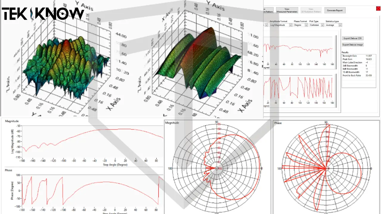
The system includes our Flagship TEKPATRF software. The software makes fully automated Radiation patterns and frequency response measurements. The software has the capabilities to calculate antenna gain, radiation efficiency, total radiated power etc. Advanced graphics capabilities allow users to plot 2D and 3D radiation patterns. The data can be exported to CSV file format for processing. The report generation capability of the software allows users to generate pdf test reports.

Our polyurethane absorbers are engineered to deliver exceptional performance in antenna chambers, ensuring precise and interference-free testing for a wide range of applications. Designed with cutting-edge technology, these absorbers provide a controlled, reflection-free environment for electromagnetic wave testing.
A Compact Antenna Test Range (CATR) enables the measurement of electrically large antennas at a considerably shorter distance compared to a traditional far-field test range. This compact setup utilizes a source antenna (feed) to emit a spherical wave toward a parabolic reflector, which then collimates the wave into a planar form to illuminate the aperture of a Device Under Test (DUT). The lowest operational frequency is influenced by factors such as the reflector’s size, edge treatment, the feed, and absorbers.
Near-field (NF) chambers are an excellent alternative to traditional far-field ranges; testing that can be accomplished on a far-field range can be accomplished on a Near-Field test range. A Near-Field chamber depends on several factors; 1) the Near-Field test method being used, 2) the size of the equipment under test, and 3) the lowest frequency being tested. Our chambers provide the necessary RF quiet environment in which to conduct many different testing applications such as for automotive and telecom wireless technology, aerospace & defense radome and RCS, and more.4

The reactive near field and the radiating near field. The reactive near field is the region where the fields are reactive, i.e., the E and H fields are out of phase by 90 degrees to each other. For propagating or radiating fields, the fields must be orthogonal to each other but in phase.
When talking about antennas the far field is the region that is at a large distance from the antenna. In the far field the radiation pattern does not change shape as the distance increases. There are three conditions which must be satisfied to ensure that the antenna is at a distance which qualifies as the far field.
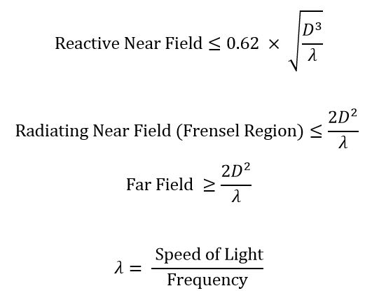
Where,
D = Antenna dimensions (Can be the length or diameter of the antenna)
f = Signal Frequency
λ = Wavelength
“Tekiknow Technologies specializes in EMI/EMC and RF shielding solutions with a focus on innovation, quality, and sustainability. We deliver reliable, customized solutions tailored to your needs.”
Copyright © 2024 – Tekiknow – All Rights Reserved Designed By Clemence Web Solutions.,